
Blogs
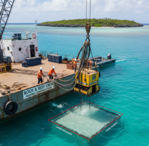
Desalination Plant Dredging: Technical Guide for Coastal Infrastructure, Seawater Intake & Outfall Systems
Summary
This pillar blog demystifies the entire lifecycle of Desalination Plant Dredging, backed by technical insights from real-world marine engineering operations. It walks stakeholders through intake channel dredging, diffuser outfall preparation, trenching, spoil management, turbidity control, environmental compliance, and long-term O&M requirements. The goal is to equip planners, consultants, and contractors with a clear, specialist-level perspective while positioning Rock and Reef as a reliable, execution-driven partner for desalination-linked dredging and marine construction across India.
Table of Contents
- Introduction
- Why Dredging Is the Backbone of Desalination Infrastructure
- Core Dredging Requirements in a Desalination Project
- 3.1 Intake Channel Dredging
- 3.2 Outfall Trench Dredging
- 3.3 Intake Structure & Foundation Preparation
- 3.4 Pipeline Corridor Dredging & Backfilling
- Types of Dredgers Needed for Desalination Works
- Technical Workflow: How a Desalination Dredging Campaign Is Executed
- Environmental & Regulatory Compliance
- Risk Factors & Mitigation Strategies
- Comparison Table: Intake vs Outfall Dredging Requirements
- Graph: Production Rates of Dredgers in Typical Desalination Sediments
- Why Desalination Plants Fail When Dredging Is Poorly Planned
- How Rock and Reef Supports Desalination EPCs End-to-End
- Final Recommendations for Project Owners
1. Introduction
Desalination plants are a strategic infrastructure. They demand precise coastal engineering, stable seabed conditions, and uninterrupted seawater intake.
And here’s the reality industry veterans know:
“The performance of a desalination plant is directly linked to the quality of dredging done during the intake and outfall development phase.”
Poor dredging = restricted flow, high sediment load, biological fouling, turbulence issues, and long-term O&M headaches.
This guide breaks down the complete dredging ecosystem behind desalination projects, practical, operational, and execution-ready.
2. Why Dredging Is the Backbone of Desalination Infrastructure
Every desalination plant depends on a stable, sediment-free intake channel and a carefully engineered outfall zone.
Key operational impacts:
- Ensures adequate seawater inflow
- Reduces pump strain
- Maintains constant Total Suspended Solids (TSS)
- Protects high-value filtration and RO components
- Ensures environmental compliance for brine discharge
Simply put, desalination without proper dredging is like a power plant without transmission lines; the system never reaches its operational potential.
3. Core Dredging Requirements in a Desalination Project

3.1 Intake Channel Dredging
Purpose:
- Create a stable pathway for seawater flow
- Achieve intake depth based on hydraulic modelling
- Remove soft silt, compact sand, or weathered rock
Technical Considerations:
- Required depth typically: -6m to -14m
- Target turbidity limits: 5–20 NTU, depending on region
- High-accuracy excavation is needed around intake screens
3.2 Outfall Trench Dredging
Purpose:
- Create a trench for the brine outfall diffuser pipelines
- Ensure controlled brine dispersion
Key Technical Points:
- Trench depth: 1.5m–4m below the existing seabed
- Gradient and slope are critical
- Outfall zones often have environmental restrictions
3.3 Intake Structure & Foundation Preparation
Tasks include:
- Rock dredging using BHD/CSD
- Micro-grading with grab dredgers
- Preparing stable bedding for intake wells
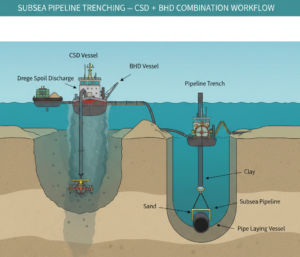
3.4 Pipeline Corridor Dredging & Backfilling
Usually executed using:
- Cutter Suction Dredgers (CSD) for continuous trenching
- Backhoe Dredgers (BHD) for precision
- TSHD for offshore sand sourcing
- Controlled backfilling to maintain pipeline integrity
4. Types of Dredgers Needed for Desalination Works
Cutter Suction Dredger (CSD)
- Best for compact sand, clay, light rock
- Ideal for intake and trenching corridors
Backhoe Dredger (BHD)
- High accuracy for intake zones & structures
- Works well in weathered rock
Grab/Clamshell Dredger
- Perfect for precision excavation around intake pits
Trailing Suction Hopper Dredger (TSHD)
- Used when offshore sand fill or large-volume transport is required
5. Technical Workflow: How a Desalination Dredging Campaign Is Executed
- Seabed Investigation (Bathymetry + Soil Report)
- Hydrographic Survey + Silt Spread Modelling
- Dredger Mobilization Plan
- Intake Channel Dredging
- Pipeline Corridor Trenching
- Backfilling with graded material
- Outfall diffuser trenching
- Rock trimming and bed preparation
- Environmental monitoring
- Post-dredging survey and verification
Each phase must align with turbidity targets, schedule milestones, and EPC commissioning timelines.
6. Environmental & Regulatory Compliance
Typical Mandates:
- Turbidity management
- Marine ecology protection
- Noise and vibration thresholds
- Disposal ground authorizations
- Bathymetric verification
- Coastal Regulation Zone (CRZ) approvals
Tools used:
- Silt curtains
- Silt screens
- Real-time turbidity sensors
- Anchor pattern optimization
7. Risk Factors & Mitigation Strategies
| Risk | Impact | Mitigation |
| Unexpected seabed rock | Schedule overrun | Pre-cutting + deploy BHD |
| High turbidity | Shutdown risk | Use silt curtains, adjust cutter speed |
| Weather downtime | Cost escalation | Seasonal scheduling |
| Pipeline floatation | Damage risk | Controlled backfilling |
| Sediment collapse | Rework | Trench stabilization |
8. Comparison Table: Intake vs Outfall Dredging Requirements
| Parameter | Intake Dredging | Outfall Dredging |
| Accuracy Required | Very High | High |
| Soil Type | Mixed/compact | Mostly soft to medium |
| Machinery | BHD + CSD | CSD + Grab |
| Environmental Sensitivity | Moderate | Very High |
| Depth Range | 6–14m | 3–10m |
| Special Needs | Intake screen protection | Diffuser slope control |
9. Graph: Production Rates of Dredgers in Typical Desalination Sediments
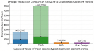
Suggested Values (m³/hour):
- CSD: 900–2500
- TSHD: 1500–8000
- BHD: 150–400
- Grab Dredger: 120–350
10. Why Desalination Plants Fail When Dredging Is Poorly Planned
- Reduced seawater intake due to siltation
- High pump wear and energy consumption
- Increased RO membrane fouling
- Brine discharge non-compliance
- Frequent shutdowns during monsoon sediment drift
- Escalating O&M costs
A desalination plant is only as good as the seabed engineering behind it.
11. How Rock and Reef Supports Desalination EPCs End-to-End
Rock and Reef offers an integrated, execution-led capability stack aligned with coastal desalination demands:
Core Marine Services
- Intake channel dredging
- Outfall Trenching
- Subsea pipeline trenching
- Controlled backfilling
- Rock dredging
- Capital & maintenance dredging
Engineering & Execution Strengths
- Multi-dredger fleet (CSD, BHD, Grab, Amphibious units)
- Hydrographic survey unit
- In-house fabrication & repair
- Marine project planning & risk management
- Coastal compliance experience
- Zero-compromise HSE protocols
12. Final Recommendations for Project Owners
For desalination plants, the most sustainable approach is early-stage collaboration.
Key Takeaways:
- Start dredging planning immediately after concept design
- Allocate budget for seabed surveys
- Select dredgers based on soil, not availability
- Plan trenching in alignment with pipeline installation windows
- Prioritize turbidity control to avoid regulatory bottlenecks
If you’re planning a desalination project intake, outfall or full marine civil package, Rock and Reef stands ready to deliver a dependable, execution-driven solution with the technical maturity your project deserves.
